PARTS
OF THE METER
FRONT OF THE METER
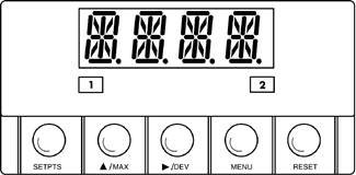
Figure 5-1 shows each part of the front of the meter. Table 5-1
on the next page gives a brief description of each part.
1 - Setpoint 1 Status
2 - Setpoint 2 Status |
 Figure
5-1. Front-Panel Illustration
|
Front-Panel Part Description
Table 5-1
|
1
|
-1.9.9.9.
or 9.9.9.9.
4-digit 14 segment, 0.54" high LED display with programmable decimal
point.
|
|
2
|
SETPOINT
LED
These LEDs labeled 1 and 2 display the status of setpoints 1 and
2. |
3

|
SETPTS
BUTTON
This button functions only in the run mode. When the meter is in
the run mode, press this button to sequentially recall the previous
setpoint settings. After using the  /MAX
and /MAX
and  /DEV
buttons to alter these settings as desired, press the SETPTS
button to store these new values. /DEV
buttons to alter these settings as desired, press the SETPTS
button to store these new values.
Unless you press the SETPTS button within 20 seconds to store
your input, the meter will scroll to setpoint 2 and retain the last
value stored.
If the dual relay option is not installed, pressing the SETPTS
button will display "V.-03" which is the meter's software
version. |
|
4
|
 /MAX
BUTTON /MAX
BUTTON
During the run mode, press the  /MAX
button to recall the PEAK reading since the last press
of the RESET button. To return to the current readings without
resetting the PEAK reading, press the /MAX
button to recall the PEAK reading since the last press
of the RESET button. To return to the current readings without
resetting the PEAK reading, press the  /MAX
button. To reset the PEAK reading, press the RESET
button. /MAX
button. To reset the PEAK reading, press the RESET
button.
During the configuration mode, use the  /MAX button to change the values of the flashing digit shown
on the display and/or toggle between menu choices, such as "R.1=F"
or "R.1=C".
When configuring your setpoint values, press the  /MAX
button to increment the flashing digit from 0 to 9 by 1's. /MAX
button to increment the flashing digit from 0 to 9 by 1's. |
|
5
|
 /DEV
BUTTON /DEV
BUTTON
During the run mode press the  /DEV
button to display the deviation from setpoint 1. /DEV
button to display the deviation from setpoint 1.
When configuring your setpoint values, press the  /DEV
button to scroll to the next digit. /DEV
button to scroll to the next digit. |
|
6
|
MENU
BUTTON
In the run mode, press the MENU button to terminate
the current measuring process and enter you into the configuration
mode. (Note: only if you have installed the lockout jumpers on
the main board.)
In the configuration mode, press the MENU button to store
changes in the non-volatile memory and then advance you to the
next menu item.
|
7

|
RESET BUTTON
If you hard reset (press the MENU button followed by
the RESET button) or power off/on the meter, it shows "RST",
followed by "T/C".
In the setpoint mode, press the RESET button to reset the
setpoints. The meter shows "SP.RS" and returns to the run
mode.
In the configuration mode, press the RESET button once to
review the previous menu. Press the RESET button twice to
perform a hard reset and return to the run mode. In the peak mode,
press the RESET button to reset peak value. The meter shows
"PK.RS" and return to the run mode.
When in setpoint or configuration mode, if the meter shows 9999
or -1999 with all flashing digits, the value has overflowed. Press
the  /MAX
button to start a new value. /MAX
button to start a new value. |
REAR
OF THE METER
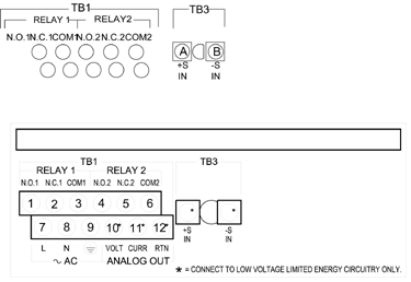
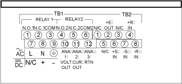
Figure 5-2 shows the connector label mounted at the top of the meter housing.
Table 5-2 gives a brief description of each connector at the rear of the
meter.

Figure 5-2a. Connector Label (AC Powered)

Figure 5-2. Connector Label AC/DC Powered
Rear
Connector Description
Table 2-2
|
CONNECTOR
|
DESCRIPTION |
|
TB1-1
|
Setpoint 1: Normally open (N.O.1) connection |
|
TB1-2
|
Setpoint 1: Normally closed (N.C.1) connection |
|
TB1-3
|
Setpoint
1: Common 1(COM1) connection |
|
TB1-4
|
Setpoint
2: Normally open (N.O.2) connection |
|
TB1-5
|
Setpoint
2: Normally closed (N.C.2) connection |
|
TB1-6
|
Setpoint
2: Common 2(COM2) connection |
|
TB1-7
|
AC
line connection (no connections on dc-powered units) |
|
TB1-8
|
AC
Neutral connection (+ Input on DC powered units) |
|
TB1-9
|
AC earth ground (dc-power return on dc-powered units) |
|
TB1-10
|
Analog
voltage output |
|
TB1-11
|
Analog
current output |
|
TB1-12
|
Analog
Return |
|
TB3-A
|
+TC:
Input |
|
TB3-B
|
-TC:
Input |
|
TB5-1
|
Isolated
Analog Voltage Output |
|
TB5-2
|
Isolated Analog Current Output |
|
TB5-3
|
Isolated
Analog Output Return |
|
J1
(1-2)
|
Remote
tare connection with a momentary switch |
|